FPGAを使ってShader芸で遊びます.
使用したFPGAボードは,Tang Mega 138K ProDock(Sipeed) です.画面は,ボードのHDMIコネクタからDVIで出力します.
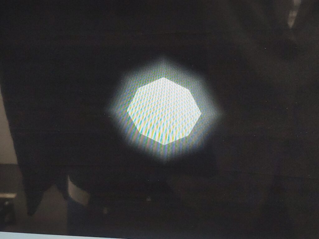
まずは,フラグメント・シェーダで球(っぽいもの)を描画します.
●topモジュール
・PLL(Gowin IP)
DVI出力するために,ピクセルクロックとシリアルクロック(ピクセルクロック×5)を生成します.
・タイミング ジェネレータ -video_timing-
1,650×720でDVI出力するための同期信号を生成します.よくある回路なので,Claude Codeが生成したものをそのまま使えます.ただし,FullHDで試した時は,解像度1920に対して60fps だとブランキングを入れて2200を使うことが多いですが,そこのカウンタが11ビットになっていて,永遠にDataEnableが立たない状態でした.
・シェーダー -shader-
中央に,Sphere(っぽいもの)を書くシェーダーです.簡単のため今回は,R=G=B
・DVI_TX_Top(Gowin IP)
DVI出力用のモジュールです.
Verilog
module top (
    input  wire clk,
    input  wire rst_n,

    // DVI TMDS output (HDMI connector)
    output wire tmds_clk_p,
    output wire tmds_clk_n,
    output wire [2:0] tmds_data_p,
    output wire [2:0] tmds_data_n,
    output logic[5:0] state_led
);

assign state_led[0] = rst;   // board LED
assign state_led[1] = rst_n; // board LED
assign state_led[2] = de;    // board LED

// Clock Generation
wire clk_pixel;
wire clk_tmds;
wire pll_lock;

    Gowin_PLL pll_inst(
        .clkin(clk),         //input  clkin
        .clkout0(clk_tmds),  //output clkout0
        .clkout1(clk_pixel), //output clkout1
        .lock(pll_lock),     //output lock
        .reset(~rst_n)       //input  reset
);

wire rst = ~rst_n | ~pll_lock;

wire [10:0] hcount;
wire [10:0] vcount;
wire hsync, vsync, de, field_start;

//Timing Generator
video_timing u_timing (
    .clk      (clk_pixel),
    .rst      (rst),
    .hcount   (hcount),
    .vcount   (vcount),
    .hsync    (hsync),
    .vsync    (vsync),
    .de       (de),
    .field_start(field_start)
);

// Shader Pixel Generator
wire [7:0] r_out, g_out, b_out;
wire shader_de;

shader u_shader (
    .clk (clk_pixel),
    .x   (hcount),
    .y   (vcount),
    .r    (r_out),
    .g    (g_out),
    .b    (b_out)
);

// DVI output
DVI_TX_Top your_instance_name(
	.I_rst_n(rst_n),             //input I_rst_n
	.I_serial_clk(clk_tmds),     //input I_serial_clk
	.I_rgb_clk(clk_pixel),       //input I_rgb_clk
	.I_rgb_vs(vsync),            //input I_rgb_vs
	.I_rgb_hs(hsync),            //input I_rgb_hs
	.I_rgb_de(de),               //input I_rgb_de
	.I_rgb_r(r_out),             //input [7:0] I_rgb_r
	.I_rgb_g(g_out),             //input [7:0] I_rgb_g
	.I_rgb_b(b_out),             //input [7:0] I_rgb_b
	.O_tmds_clk_p(tmds_clk_p),   //output O_tmds_clk_p
	.O_tmds_clk_n(tmds_clk_n),   //output O_tmds_clk_n
	.O_tmds_data_p(tmds_data_p), //output [2:0] O_tmds_data_p
	.O_tmds_data_n(tmds_data_n)  //output [2:0] O_tmds_data_n
);

endmoduleExpand
●シェーダー -shader-
入力するのは,X,Y座標のみです.
Verilog
module shader (
    input wire clk,
    input wire [11:0] x,
    input wire [11:0] y,

    output reg [7:0] r,
    output reg [7:0] g,
    output reg [7:0] b
);

localparam [11:0] CAMERA_x = 1650 / 2;
localparam [11:0] CAMERA_y = 720 / 2;

// =====================
// Sphire
// =====================
logic[7:0] pixel_value;

function [11:0] length;
    input [15:0] val1;
    input [15:0] val2;

    length = ( (((val1>val2)?val1:val2) << 16'd4) + (((val1<val2)?val1:val2) << 16'd3)) >> 16'd4;
endfunction

logic[11:0] c_x, c_y; // current pixel position(x,y) from center
logic[11:0] sphere_length;

assign c_x = (x < CAMERA_x)?CAMERA_x - x: x - CAMERA_x;
assign c_y = (y < CAMERA_y)?CAMERA_y - y: y - CAMERA_y;
assign sphere_length = length(c_x,c_y);

always_ff @(posedge clk)begin

    if (sphere_length[11:0] <100)begin
        pixel_value <= 8'hff;
    end else begin
        pixel_value <= (8'hff < (sphere_length[11:0]*2-90))?8'b0:(8'hff - (sphere_length[7:0]*2-90));
    end
    r <= pixel_value;
    g <= pixel_value;
    b <= pixel_value;
end

endmodule●タイミングジェネレータ -video_timing-
Claude Codeに生成させたものをベースにしているので,コメントは参考にしないでください.
Verilog
// ============================================================
// Video Timing Generator
// 1280×720 @ 30 Hz  Pixel Clock: 37.125 MHz
//
// CEA-861 720p ブランキング (30 Hz = 60 Hz の半フレームレート)
// H: Active=1280  FP=110  Sync=40(+)  BP=220  Total=1650
// V: Active=720   FP=5    Sync=5(+)   BP=20   Total=750
// Pixel clock: 37.125 MHz
// Frame rate:  37.125 MHz / (1650 × 750) = 30.000 Hz
// Hsync/Vsync polarity: positive
// ============================================================
module video_timing (
    input  wire        clk,
    input  wire        rst,
    output reg  [11:0] hcount,      // 0 .. H_TOTAL-1  (max 1649, 11bit)
    output reg  [10:0] vcount,      // 0 .. V_TOTAL-1  (max 749,  10bit)
    output wire        hsync,
    output wire        vsync,
    output wire        de,           // data enable (active area)
    output reg         field_start   // one-cycle pulse at start of frame
);

// ── Timing parameters ──────────────────────────────────────
localparam H_ACTIVE = 1280;
localparam H_FP     = 110;
localparam H_SYNC   = 40;
localparam H_BP     = 220;
localparam H_TOTAL  = H_ACTIVE + H_FP + H_SYNC + H_BP; // 1650

localparam V_ACTIVE = 720;
localparam V_FP     = 5;
localparam V_SYNC   = 5;
localparam V_BP     = 20;
localparam V_TOTAL  = V_ACTIVE + V_FP + V_SYNC + V_BP;  // 750


// ── Counters ───────────────────────────────────────────────
always @(posedge clk or posedge rst) begin
    if (rst) begin
        hcount      <= 0;
        vcount      <= 0;
        field_start <= 0;
    end else begin
        field_start <= 0;
        if (hcount == H_TOTAL - 1) begin
            hcount <= 0;
            if (vcount == V_TOTAL - 1) begin
                vcount      <= 0;
                field_start <= 1;
            end else begin
                vcount <= vcount + 1;
            end
        end else begin
            hcount <= hcount + 1;
        end
    end
end

// ── Output signals ─────────────────────────────────────────
assign hsync = (hcount >= H_BP) && (hcount < (H_BP + H_SYNC));
assign vsync = (vcount >= V_BP) && (vcount < (V_BP + V_SYNC));
assign de    = (hcount > (H_BP + H_SYNC)) && (hcount < (H_BP+H_SYNC + H_ACTIVE)) && (vcount > (V_BP + V_SYNC)) && (vcount < (V_BP + V_SYNC + V_ACTIVE));

endmoduleExpand